Serial Communication in Advanced Ladder
See also: Serial Port Communication
See also: Project Toolbox for Advanced Ladder
Topic Menu

|
Serial Port Operation |

|
How to Modbus RTU |

|
Advanced Modbus TCP |
Home > View > Project Toolbox > Networking - CsCAN
Serial Operations Topics:
Serials Operations provide a way to communicate via program logic. Several different protocols and methods are contained within and are grouped together by the type of communication they are for. For ASCII![]() ASCII - American Standard Code for Information Interchange - ASCII-coded characters are single-byte values in the range of 0 (zero) to 127. Codes in the range 128 to 255 are not defined by the ASCII standard, but rather by the equipment manufacturer. serial communications use, such as with bar code readers, weight scales, etc., please refer to Using Serial Ports [LINK: Using Serial Ports (new Help section, content already exists in old help file)] for an understanding of how incoming data is processed.
ASCII - American Standard Code for Information Interchange - ASCII-coded characters are single-byte values in the range of 0 (zero) to 127. Codes in the range 128 to 255 are not defined by the ASCII standard, but rather by the equipment manufacturer. serial communications use, such as with bar code readers, weight scales, etc., please refer to Using Serial Ports [LINK: Using Serial Ports (new Help section, content already exists in old help file)] for an understanding of how incoming data is processed.
Note: The CsCAN![]() Horner APG's proprietary network protocol that runs on the Bosch CAN network specifications. Prior to the advent of the OCS. and CANopen
Horner APG's proprietary network protocol that runs on the Bosch CAN network specifications. Prior to the advent of the OCS. and CANopen![]() A CAN-based communication system. It comprises higher-layer protocols and profile specifications. CANopen has been developed as a standardized embedded network with highly flexible configuration capabilities. portions of the Comm Operations may or may not be enabled depending on hardware configuration. The example Comm Operations toolbar pictured uses an OCS product with dual CAN ports; one configured for CsCAN and the other for CANopen.
A CAN-based communication system. It comprises higher-layer protocols and profile specifications. CANopen has been developed as a standardized embedded network with highly flexible configuration capabilities. portions of the Comm Operations may or may not be enabled depending on hardware configuration. The example Comm Operations toolbar pictured uses an OCS product with dual CAN ports; one configured for CsCAN and the other for CANopen.
Open Communications Overview 
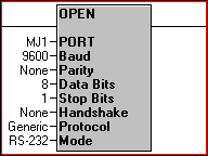
The Open Communications Port function provides a way to open any of the available serial ports that are not otherwise in use by the
The modes/protocols available are
-
Generic ASCII, used for bar code readers, weight scales, and other devices which could work with a simple ASCII terminal program
-
Modbus
 A popular, de-facto standard protocol that allows industrial devices from multiple manufacturers to easily share data in real-time. Can be run over serial communications such as RS-232 and RS-485, as well as Ethernet. Modbus over Ethernet is usually referred to as Modbus TCP/IP.RTU RTU - Remote Terminal Unit - A microprocessor-based device that monitors and controls field devices, that then connects to plant control or SCADA (supervisory control and data acquisition) systems., for either Modbus Master or Modbus Slave communications
 -
Modbus ASCII, for either Modbus Master or Modbus Slave communications
Serial Ports opened with this function will remain open until the Close Communications Port function [Close Communications Port] is used or the OCS controller is put into STOP mode. Any Open function that is used when the selected port has already been opened by another Open Port function will change the parameters accordingly.
Note on OCS as a serial Modbus Master: Even though it is still possible to build highly customized serial Modbus Master communications using logic, Modbus Master functionality has been largely supplanted by the much easier-to-use . For any single port, the Open function and the Protocol Configuration cannot be used at the same time.
Note on OCS as a serial Modbus Slave: Using this function, along with the Modbus Slave function, is the only way to enable serial Modbus Slave communications.
Note on MJ1 programming port: The MJ1 port is the default Cscape programming port for nearly every OCS, though USB and Ethernet programming are also automatically available on most OCS products. Using the Open function on MJ1 will open it for the specified parameters and close it to Cscape programming use. Closing the MJ1 port with the Close Communication Port in Advanced Ladder function will disable whatever Open parameters were last used and will re-open the port to Cscape programming. If it is absolutely required to use MJ1 for communications and an RS-232 programming port is also required for Cscape access, it is possible to reassign the programming port to another port in the System Menu of the OCS controller. See System Settings in
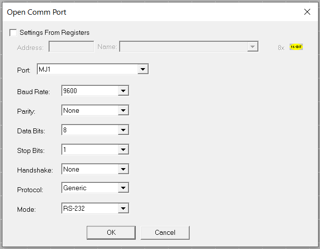
Settings from Registers: It is possible to “hard code” the settings by leaving this box unchecked and using the dropdown selections for each parameter. Alternately, the settings may be obtained dynamically from an array/registers by checking this box. Specifying “Settings From Registers” and an array element/register will use the values in 8 consecutive elements/registers for these settings. See remaining parameters for values to use when this box is checked.
Port: The serial port to open with this function. Options will vary per OCS model and may include MJ1, MJ2, MJ3, and COM. Older OCS models may include PORT 1, PORT2, and CN1. For “Settings From Registers”:
-
0 = MJ1
-
1 = MJ2 (or CN1 for NX)
-
2 = CN1 (for QX only)
-
3 = MJ3
Baud Rate: Select the baud rate to match the device being communicated with. For “Settings From Registers”:
-
0 = 300 baud
-
1 = 600 baud
-
2 = 1200 baud
-
3 = 2400 baud
-
4 = 4800 baud
-
5 = 9600 baud
-
6 = 19200 baud
-
7 = 38400 baud
-
8 = 57600 baud
-
9 = 115200 baud
-
10 = 14400 baud
-
11 = 28800 baud
-
12 = 10400 baud
Parity: Select the parity to match the device being communicated with (None, Odd, Even) . For “Settings From Registers”:
-
0 = None
-
1 = Odd
-
2 = Even
Data Bits: Select the data bits to match the device being communicated with (7, 8) . For “Settings From Registers”:
-
2 = 7 Data Bits
-
3 = 8 Data Bits
Stop Bits: Select the stop bits to match the device being communicated with (1, 2) . For “Settings From Registers”:
-
0 = 1 Stop Bits
-
1 = 2 Stop Bits
Handshake![]() Handshaking is an automated process that sets parameters for communication between two different devices before normal communication begins. Much like the way a human handshake sets the stage for the communication to follow, the computing handshake provides both devices with the basic rules for the way data is to be shared between them. These rules can include transfer rate, coding alphabet, parity, and interrupt procedure.: Options will vary with OCS used. For RS-232 comms, this should match wiring and the device being communicated with (None, Xon/Xoff, Hardware). For the RS-485
Handshaking is an automated process that sets parameters for communication between two different devices before normal communication begins. Much like the way a human handshake sets the stage for the communication to follow, the computing handshake provides both devices with the basic rules for the way data is to be shared between them. These rules can include transfer rate, coding alphabet, parity, and interrupt procedure.: Options will vary with OCS used. For RS-232 comms, this should match wiring and the device being communicated with (None, Xon/Xoff, Hardware). For the RS-485![]() An EIA standard that specifies electrical characteristics of drivers and receivers for use in serial communications. Electrical signaling is balanced and multipoint systems are supported. standard, “Multidrop Full” should be used for RS-485 4-wire connections and “Multidrop Half” MUST be used for 2-wire connections, in conjunction with proper DIP switch settings on some models. For “Settings From Registers”:
An EIA standard that specifies electrical characteristics of drivers and receivers for use in serial communications. Electrical signaling is balanced and multipoint systems are supported. standard, “Multidrop Full” should be used for RS-485 4-wire connections and “Multidrop Half” MUST be used for 2-wire connections, in conjunction with proper DIP switch settings on some models. For “Settings From Registers”:
-
0 = None
-
1 = Xon/Xoff
-
2 = Hardware
-
3 = Multidrop Full
-
4 = Multidrop Half
-
5 = Radio Modem
Protocol: The desired protocol for which to open the port
-
1 = CsCAN
-
2 = Generic ASCII
-
3 = Modbus RTU
-
4 = Modbus ASCII
-
5 = Modbus TCP (Only for XL series with HE-XEC option board)
Mode: The standard to use with this function, restricted to RS-232 and RS-485 unless an option card is installed.
-
0 = RS232
-
1 = RS485
-
2 = Modem
-
3 = Ethernet
-
4 = Fiber A
-
5 = Fiber B
-
6 = GSM Dual
-
7 = GSM Quad
-
8 = Radio 900MHz
-
9 = Radio Zigbee
Power Flow
The Open Communications Port function executes immediately and entirely as soon as it receives power from the incoming rung. The port may be immediately used for configured communications assuming success.
The Open Communications Port function will execute on every scan that it has received power from the incoming rung.
The Open Communications Port function will pass power flow to the next function on the rung unless a port that does not exist is specified (possible with dynamic settings).
There is no need for any further functions to exist to the right of the Open Communications Port function on the rung. The function’s result is considered an output.
Return to the Top: Serial Communication in Advanced Ladder
ASCII Character Codes
The following are 8-bit ASCII![]() ASCII - American Standard Code for Information Interchange - ASCII-coded characters are single-byte values in the range of 0 (zero) to 127. Codes in the range 128 to 255 are not defined by the ASCII standard, but rather by the equipment manufacturer. characters and their character codes.
ASCII - American Standard Code for Information Interchange - ASCII-coded characters are single-byte values in the range of 0 (zero) to 127. Codes in the range 128 to 255 are not defined by the ASCII standard, but rather by the equipment manufacturer. characters and their character codes.
| Char | Dec | Hex |
|---|---|---|
| NULL |
0 | 00 |
| SOH | 1 | 01 |
| STX | 2 | 02 |
| ETX | 3 | 03 |
| EOT | 4 | 04 |
| ENQ | 5 | 05 |
| ACK | 6 | 06 |
| BELL | 7 | 07 |
| BS | 8 | 08 |
| HT | 9 | 09 |
| LF | 10 | 0A |
| VT | 11 | 0B |
| FF | 12 | 0C |
| CR | 13 | 0D |
| SOH | 14 | 0E |
| SI | 15 | 0F |
| DLE | 16 | 10 |
| DC1 | 17 | 11 |
| DC2 | 18 | 12 |
| DC3 | 19 | 13 |
| DC4 | 20 | 14 |
| NAK | 21 | 15 |
| SYN | 22 | 16 |
| ETB | 23 | 17 |
| CAN | 24 | 18 |
| EM | 25 | 19 |
| SUE | 26 | 1A |
| ES1 | 27 | 1B |
| FS2 | 28 | 1C |
| GS | 29 | 1D |
| RS | 30 | 1E |
| US | 31 | 1F |
| (SPC) | 32 | 20 |
| ! | 33 | 21 |
| " | 34 | 22 |
| # | 35 | 23 |
| $ | 36 | 24 |
| % | 37 | 25 |
| & | 38 | 26 |
| ' | 39 | 27 |
| ( | 40 | 28 |
| ) | 41 | 29 |
| * | 42 | 2A |
| + | 43 | 2B |
| , | 44 | 2C |
| - | 45 | 2D |
| . | 46 | 2E |
| / | 47 | 2F |
| 0 | 48 | 30 |
| 1 | 49 | 31 |
| 2 | 50 | 32 |
| 3 | 51 | 33 |
| 4 | 52 | 34 |
| 5 | 53 | 35 |
| 6 | 54 | 36 |
| 7 | 55 | 37 |
| 8 | 56 | 38 |
| 9 | 57 | 39 |
| : | 58 | 3A |
| : | 59 | 3B |
| < | 60 | 3C |
| = | 61 | 3D |
| > | 62 | 3E |
| ? | 63 | 3F |
| @ | 64 | 40 |
| A | 65 | 41 |
| B | 66 | 42 |
| C | 67 | 43 |
| D | 68 | 44 |
| E | 69 | 45 |
| F | 70 | 46 |
| G | 71 | 47 |
| H | 72 | 48 |
| I | 73 | 49 |
| J | 74 | 4A |
| K | 75 | 4B |
| L | 76 | 4C |
| M | 77 | 4D |
| N | 78 | 4E |
| O | 79 | 4F |
| P | 80 | 50 |
| Q | 81 | 51 |
| R | 82 | 52 |
| S | 83 | 53 |
| T | 84 | 54 |
| U | 85 | 55 |
| V | 86 | 56 |
| W | 87 | 57 |
| X | 88 | 58 |
| Y | 89 | 59 |
| Z | 90 | 5A |
| [ | 91 | 5B |
| \ | 92 | 5C |
| ] | 93 | 5D |
| ^ | 94 | 5E |
| _ | 95 | 5F |
| ` | 96 | 60 |
| a | 97 | 61 |
| b | 98 | 62 |
| c | 99 | 63 |
| d | 100 | 64 |
| e | 101 | 65 |
| f | 102 | 66 |
| g | 103 | 67 |
| h | 104 | 68 |
| i | 105 | 69 |
| j | 106 | 6A |
| k | 107 | 6B |
| l | 108 | 6C |
| m | 109 | 6D |
| n | 110 | 6E |
| o | 111 | 6F |
| p | 112 | 70 |
| q | 113 | 71 |
| r | 114 | 72 |
| s | 115 | 73 |
| t | 116 | 74 |
| u | 117 | 75 |
| v | 118 | 76 |
| w | 119 | 77 |
| x | 120 | 78 |
| y | 121 | 79 |
| z | 122 | 7A |
| { | 123 | 7B |
| | | 124 | 7C |
| } | 125 | 7D |
| ~ | 126 | 7E |
| DEL | 127 | 7F |
Manufactured Specified..........................128-255..............80-FF
Return to the Top: Serial Communication in Advanced Ladder